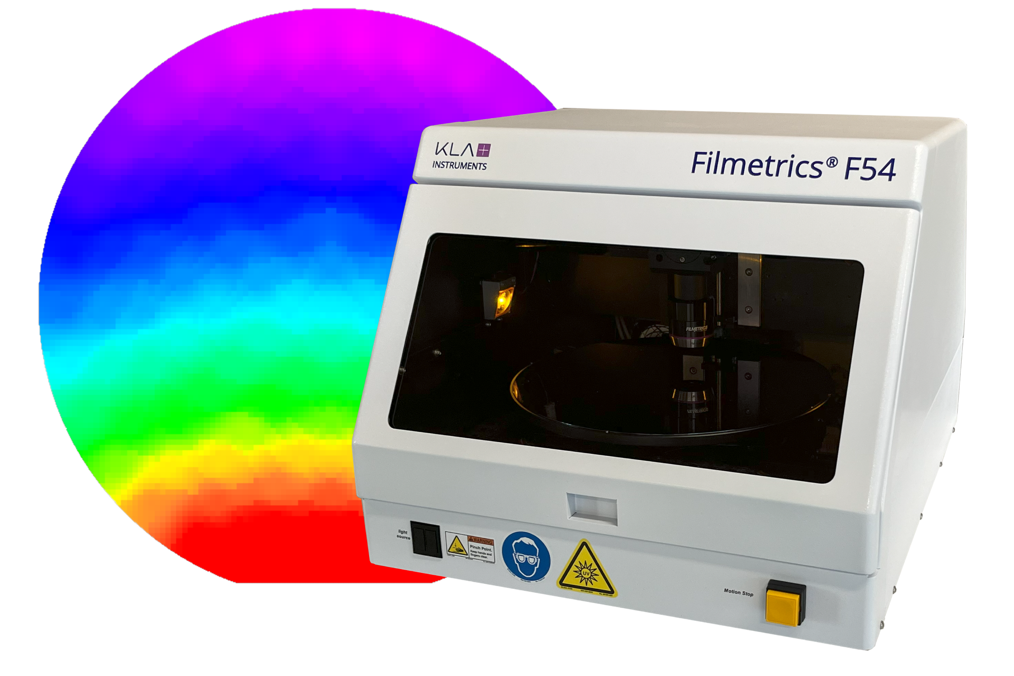
Transparent conductive thin films find extensive applications in semiconductor devices, including solar cells, liquid crystal displays, light-emitting diodes, and various sensors. Indium tin oxide (ITO) is widely used as a transparent layer due to its excellent electrical conductivity, optical transparency, and nonlinearity. ITO film deposition by sputtering is favored for its ability to produce films with a compact structure and high transmittance.
During film growth, induced film stresses can affect device fabrication and performance:
- Stress-induced wafer bow affects device planarity and subsequent production processes;
- Film stress can alter the physical device properties, potentially compromising reliability.
Experiment Overview
Nine different values of sputtered ITO film thickness were first measured using a Filmetrics® F50-UVX reflectometer from KLA Instruments™. Wafer bow and stress measurements were then performed using the KLA Instruments HRP®-260 automated stylus profiler, as shown in Figure 1. For the wafer bow measurement, the system automatically rotates the sample after each scan to generate a 3-dimensional (3D) bow map from which the software automatically calculates the 3D stress map using the Stoney equation, as shown in Figure 2. Next, the grain structure of the deposited films was evaluated by AFM, as shown in Figures 3 and 4. Finally, the elastic moduli of the ITO films were evaluated by nanoindentation using the Nano Indenter® G200X from KLA Instruments.
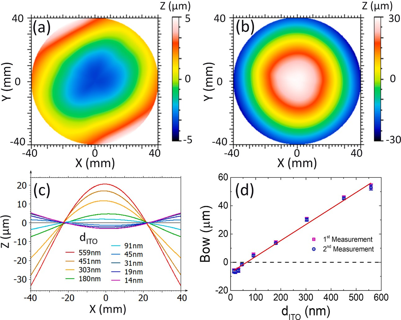
Figure 1. (a) 3D bow of ITO (14nm)/glass; (b) 3D bow of ITO (559nm)/glass; (c) 2D bow of ITO/glass with ITO thickness ranging from 14 to 559 nm; (d) Bow as a function of ITO film thickness measured at two distinct time points.
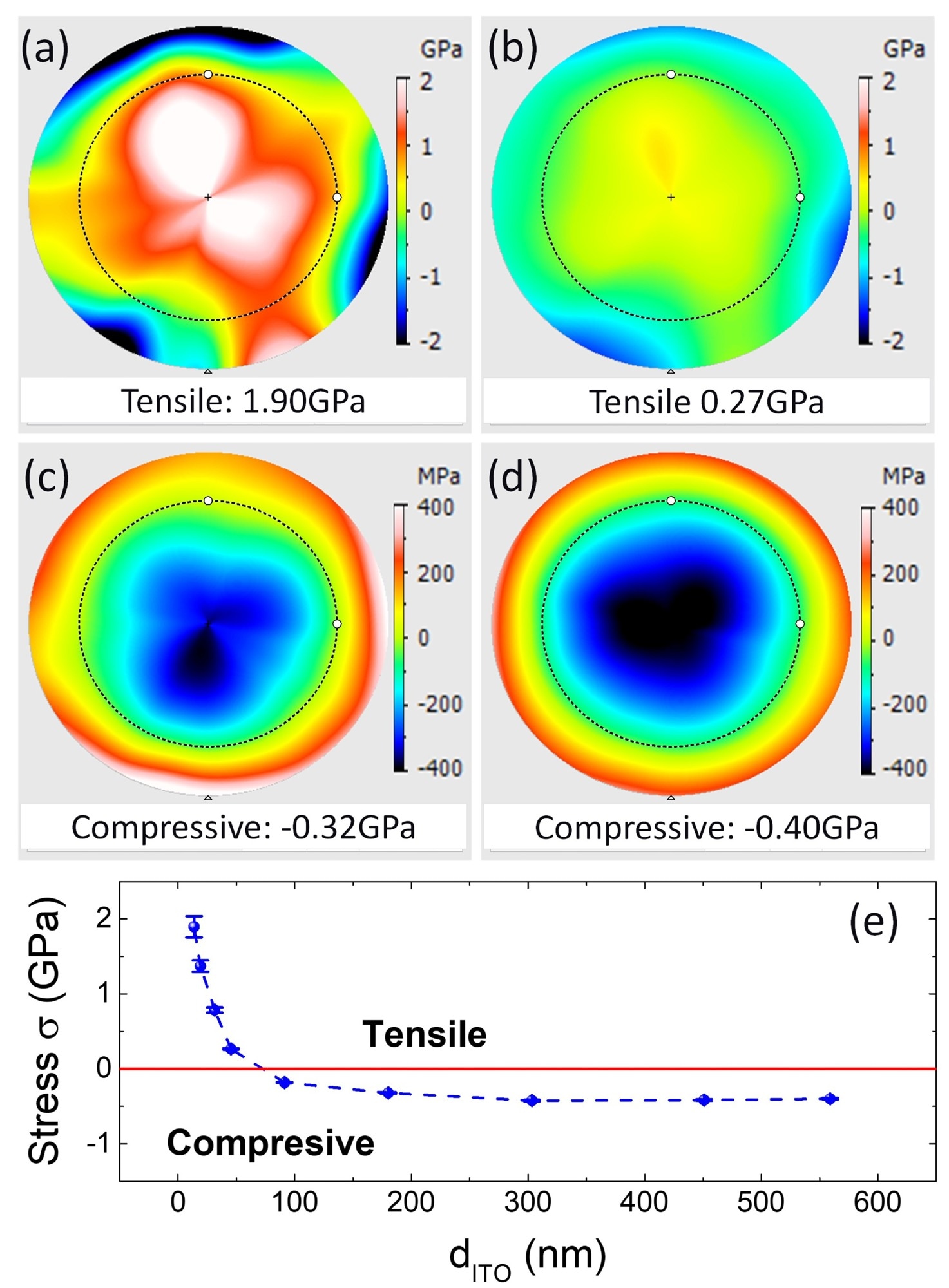
Figure 2. 3D stress of ITO/glass with different ITO thicknesses: (a) dITO = 14 nm; (b) dITO = 45 nm; (c) dITO = 180 nm; (d) dITO = 559 nm. (e) ITO film stress versus film thickness.
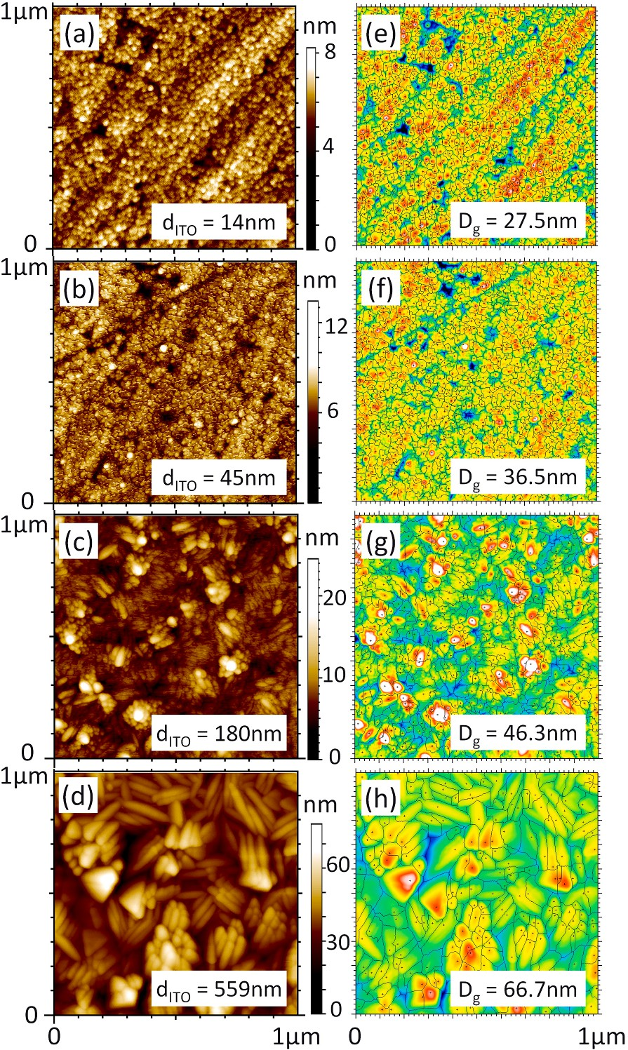
Figure 3. (a)-(d): AFM images of the ITO/glass with different ITO thicknesses; (e)-(h): Grain size analysis with Apex analysis software.
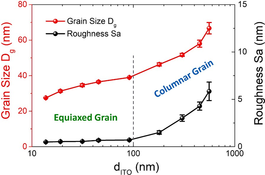
Figure 4. Grain size and surface roughness shown as a function of ITO thickness.
Summary of Results
The investigation revealed a transition of stress type from tensile to compressive as the thickness of the ITO films increased. AFM analysis of the surface morphology of the ITO films indicated a three-dimensional growth mode, with a transformation from equiaxed to columnar grain structure during deposition. Further examination revealed that the tensile stress originated from the impingement and coalescence of newly formed equiaxed grains. As the film thickness increased, fewer equiaxed grains emerged, leading to the dominance of compressive stress. The compressive stress was attributed to the incorporation of excess material in the boundaries of columnar grains.
Further Information
For additional details of the experiment and results, please read the original article as published in Thin Solid Films. For more information on the KLA Instruments metrology systems used in this experiment, please visit the KLA Instruments website:
Visit KLA Instruments at SPIE Photonics West January 30 – February 1, 2024
You are warmly invited to meet KLA's experts at SPIE Photonics West Booth 1767, January 30 – February 1, 2024, in San Francisco.
