In a number of materials, the plastic stress that can be sustained depends on strain rate through a power-law relationship: higher stresses are sustained with higher strain rates and vice versa. In a uniaxial tensile configuration, this relationship between plastic stress, σ, and strain rate,ε•u, can be expressed via the following equations:
 |
Eq. 1 |
 |
Eq. 2 |
 |
Eq. 3 |
where B* is a constant and m is the strain-rate sensitivity (SRS), which is always greater than or equal to zero. For materials showing negligible strain-rate sensitivity, m is near zero, making σ a constant. Materials with greater strain-rate sensitivity have greater values of m.
By performing a series of indentations, Lucas and Oliver showed that the strain-rate sensitivity, m, could be evaluated with each indentation performed using a different strain rate. This approach is challenging since indentations at small strain rates take so long that the results can easily be dominated by thermal drift.
The protocol proposed by Maier et al. has several practical advantages. First, the testing time and thermal drift are minimized by using fast strain rates when the applied force is small and slow strain rates when the applied force is large. The protocol suggested by Maier et al. examines the largest strain rate at the beginning of the test and examines progressively smaller strain rates as the applied force increases.
Both thermal drift and testing time are minimized this way. The protocol of Maier et al. has been implemented in a new KLA NanoSuite test method. The second benefit of the Maier protocol is that since all strain rates of interest are examined in every test, it is possible to map the spatial distribution of strain-rate sensitivity.
Sample and Instrumentation
The sample tested in this work was a NIST standard reference material (SRM) for Vickers hardness. The sample is a 1.35cm square test block of electrodeposited bright nickel, approximately 750µm thick, on an AISI 1010 steel substrate, mounted and highly polished in a thermosetting epoxy. The sample has a smooth surface, a small grain size and is resistant to corrosion and tarnish.
A KLA NanoIndenter G200 system with a Berkovich indenter was used for all testing. In order to achieve hardness and elastic modulus as a continuous function of penetration depth, KLA’s Continuous Stiffness Measurement (CSM) option was also used.
Test Method
Using the test method “G-Series XP CSM Strain-Rate Sensitivity”, twelve indentation tests were performed. Table 1 summarizes testing inputs. This test method enables the user to prescribe a penetration that must be achieved prior to strain-rate cycling (Displacement, Initial).
Table 1. Summary of inputs used to measure the strain-rate sensitivity of a Ni Vickers SRM by the method “G-Series XP CSM Strain-Rate Sensitivity.”
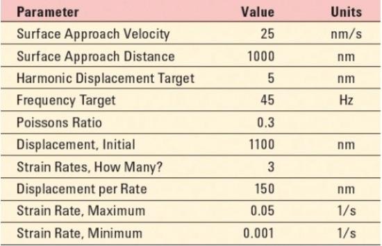
On achieving initial penetration, the method prescribes cycling between a test strain rate and a base strain rate. The test strain rate is executed in the first part of the cycle; the base strain rate is executed in the second part of the cycle. Figure 1 shows the strain-rate history for each indentation test on the Ni SRM.
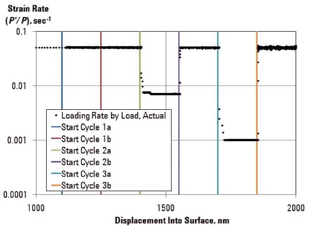
Figure 1. Strain-rate cycling imposed on the test sample. In the first part of the cycle, the test strain rate is imposed. In the second part of the cycle, the base strain rate is imposed.
Results and Discussion
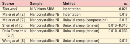
The most important results are summarized in Table 2. A survey of strain-rate-sensitivity values measured by others for fine-grained Ni is shown in Table 3.
Table 2. Summary of results.
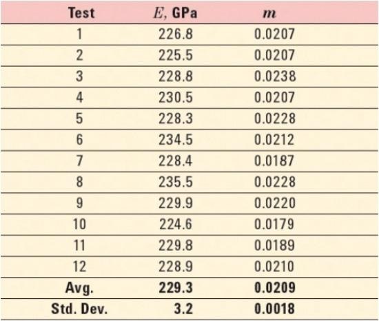
Table 3. Survey of SRS (m) values measured by others on fine-grained Ni.
The continuous elastic modulus during strain-rate cycling for one typical test is shown in Figure 2. As expected, the modulus did not change significantly during strain-rate cycling. For each cycle modulus is reported by averaging the continuous measurements that fall within 80–90% of the displacement range for the base-strain-rate segment of the cycle. These measurements are plotted as green data points in Figure 2.
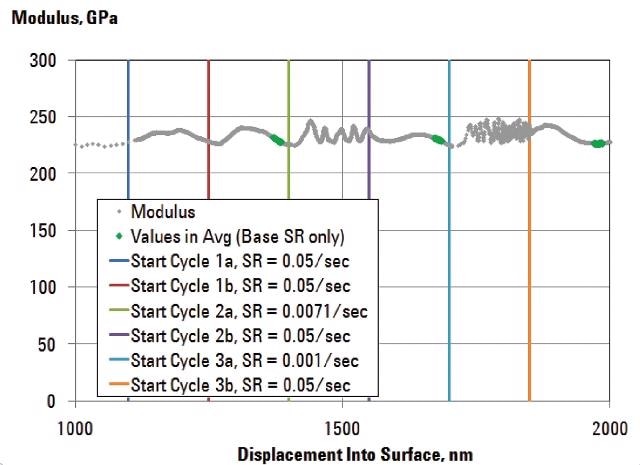
Figure 2. Modulus during strain-rate cycling for one typical test. As expected, modulus is not sensitive to strain rate.
The modulus value reported for each test in Table 2 is the average of the three cycle-level results for that test. The average over all tests, 229GPa, is 15% higher than the nominal value of 200GPa for pure nickel.
One can use finite-element simulations of indentations into a material with nickel-like properties for further investigations, since finite-element simulations allow a comparison between contact area determined by the Oliver-Pharr model and contact area determined from the finite-element mesh.
Figure 3 shows the continuous hardness measured during strain-rate cycling for a typical test. For each test strain rate, the hardness values within 80–90% of the displacement range for the segment are averaged to report a single value of hardness; data within this range for each cycle are plotted as black symbols in Figure 3.
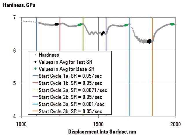
Figure 3. Hardness during strain-rate cycling. Sensitivity to strain rate is evident. Black symbols denote data used to calculate the hardness for each test strain rate. Green symbols denote data used to calculate the hardness for each base strain rate.
Figure 4 shows ln(H) vs. ln(ε•) for all 12 tests. The linearity of these results supports the hypothesis that this material is well described by Equation 2.
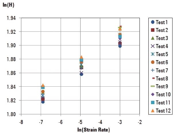
Figure 4. Plot of ln(H) vs. ln(ε•) for each of 12 tests. Slope of ln(H) in respect to ln(ε•) for each test gives the strain-rate sensitivity, m, for that test. Linearity of these data demonstrates that strain-rate sensitivity for this material is well modeled by Eq. 2.
For all 12 tests, Figure 5 shows hardness associated with the base strain rate for each cycle.
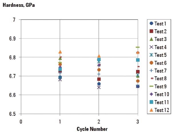
Figure 5. Hardness measured during the base-strain-rate segment of each cycle. Lack of any trend with cycle number demonstrates that the same hardness is measured when the same strain rate is applied, despite increasing penetration.
Conclusion
An experimentally robust test method has been implemented in KLA NanoSuite for measuring strain-rate sensitivity via instrumented indentation. The method overcomes the challenges associated with long testing times by imposing small strain rates only when the applied force is large.
With this method, the strain-rate sensitivity of a sample of nickel sold by NIST as a Vickers SRM was measured to be m = 0.021. This value is in good agreement with values obtained by others on similar materials using both instrumented indentation and uniaxial creep testing.

This information has been sourced, reviewed and adapted from materials provided by Nanomechanics, Inc., a KLA-Tencor company.
For more information on this source, please visit KLA.