Minus K® isolators typically use three isolators stacked in series: a tilt-motion isolator on top of a horizontal-motion isolator on top of a vertical-motion isolator.

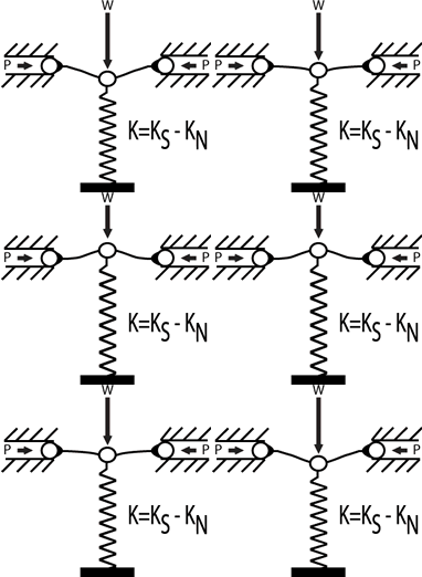
Figure 1
Figure 1 is an illustration of a vertical-motion isolator. The spring is joined to an NSM in a standard way. The NSM is made up of two flexures propped up at the outside facing ends and linked to the spring at the inward facing ends, and inserted in compression by forces P. The weight, represented by the letter W in Figure 1, keeps the spring packed down to the functioning point of the isolator. The rigidness of the spring is equal to KS and the degree to which the rigidness if minus is represented as KN. The scale of negative rigidness is a function of the construct of the flexures and load P. The rigidness of the isolator (K) can be worked out from the equation K= KS-K N., the isolator rigidness can be forced to advance zero as the spring supports the weight W.
Mechanism of Horizontal-Motion Isolation
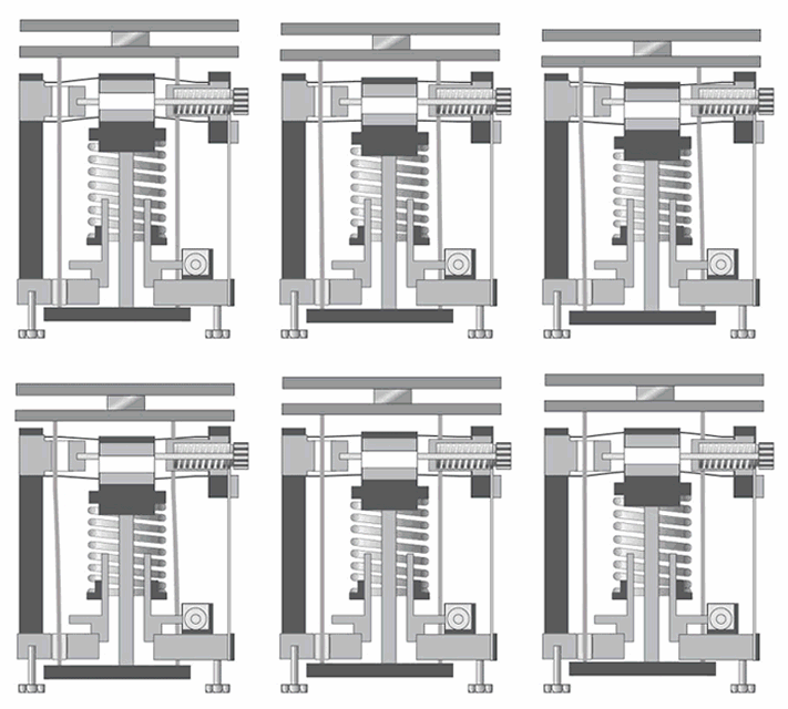
Figure 2 is an illustration of a horizontal-motion isolation mechanism that involves two beam-column isolators. The two isolators act separately similar to two secure-uninhibited beam columns inserted axially by a weight load (W). If W was not present, there would be horizontal stiffness (KS) in the beam-columns. However, in the presence of the weight load, the “beam-column” effect decreases the lateral rigidness caused by bending.
This phenomenon is equal to a NSM mixed with a horizontal spring, where K=KS-KN is the horizontal rigidness, and KN represents the degree to which the beam-column effect. Horizontal rigidness can be forced to advance zero by loading the beam-columns up to the point of their critical collapsing point.
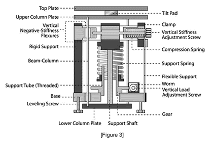
Figure 3 shows a schematic of a negative-stiffness vibration isolator incorporating the isolators of Figures 1 and 2. A tilt pad serves as the tilt-motion isolator. A vertical stiffness adjustment screw is used to adjust the compression force on the negative-stiffness flexures thereby changing the vertical stiffness. A vertical load adjustment screw is used to adjust for varying weight loads by raising or lowering the base of the support spring to keep the flexures in their straight, unbent operating position. This feature can be automated in single-isolator systems and to achieve automatic leveling in multiple-isolator systems.


This information has been sourced, reviewed and adapted from materials provided by Minus K Technology.
For more information on this source, please visit Minus K Technology.