A team of researchers recently published a paper in the journal Scientific Reports that investigated the effectiveness of a new electrospinning device for synthesizing nanofiber in both near- and far-field conditions.

Study: A new versatile x–y–z electrospinning equipment for nanofiber synthesis in both far and near field. Image Credit: vrx/Shutterstock.com
Background
Nanomaterials, specifically nanofibers, have gained considerable attention owing to their potential application in catalysis, electronics, and medicine. Nanofibers can act as architectural elements in tissue scaffolds and as a foundation for intelligent textiles and artificial skin. Additionally, these fibers can be used as an effective bioactive molecule delivery system for therapeutic applications.
Electrospinning, template-assisted synthesis, self-assembly, and solvent casting methods are commonly used to synthesize nanofibers. Among them, electrospinning is often preferred for nanofiber synthesis owing to its ability to electrospun and produce composite, synthetic, and natural nano- and microfibers of different porosities, textures, morphologies, and materials in scalable quantities. Moreover, the method can also be used to guide the assembly of nanofibers in order to fabricate complex three-dimensional (3D) structures for different applications such as wound dressing and drug delivery.
Electrospinning equipment is the most critical part of the electrospinning process. Several attempts were made to improve the electrospinning equipment design to enhance its performance. For instance, a rigorous mathematical approach and the use of a magnetic field were proposed in a previous study to accurately predict the jet behavior and control the electrospinning process, respectively.

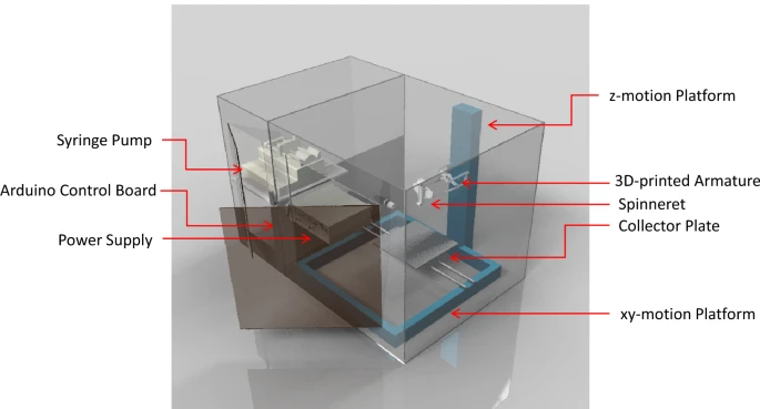
Figure 1. An illustration of the versatile electrospinning equipment for large-area, high precision deposition, writing, and printing of electrospun nanofibers. © Calzado‑Delgado, M., Yeung, K. L. et al. (2022)
New Device Design
In this study, researchers designed a new electrospinning device that can achieve a smooth transition from the far-field, large-area electrospinning to near-field, high-precision fiber printing. The proposed device was developed to craft and assemble nanofibers manufactured from polyvinyl alcohol (PVA), polyethylene oxides (PEO), and hydroxypropyl methylcellulose (HPMC) into complicated structures such as aligned fibers, nano-walls, and meshes.
Collector plate, xy-motion platform, z-motion platform, 3D-printed armature spinneret, syringe pump, Arduino control board, and power supply were used as the key components in the proposed electrospinning device. The device was kept in a transparent chamber equipped with dehumidifier/humidifier units and a set of DC fans to maintain the humidity and temperature during electrospinning. Additionally, the chamber was connected to a local exhaust to eliminate/vent solvents.
The electrospun fiber mat, written fiber patterns, printed fibers were collected on glossy paper, indium tin oxide (ITO) glass and conducting carbon, and thin copper wires respectively. All electrospinning operations were performed at 65% relative humidity and room temperature. An Olympus BH2-MJLT optical microscope was employed to investigate the electrospun samples, while the nanofiber diameter was determined using Image J.
An electrospun PVA fiber loaded with 10 wt.% amoxicillin and clavulanic acid was sandwiched between HPMC layers and the resultant HPMC/PVA/HPMC sample was evaluated for bactericidal, wound healing, and drug release. Gram-positive Staphylococcus aureus (S. aureus), Enterococcus faecalis (E. faecalis), and Gram-negative Escherichia coli (E. coli) were used during the evaluation of bactericidal properties.
The equipment was designed to achieve independent and rapid x-y-z movements without compromising precision movements and accurate positioning to use it in a versatile manner. Apart from precision movements, the electric field within the device was also precisely controlled to control fiber deposition, size, and diameter. These factors helped in achieving highly reproducible fiber production.

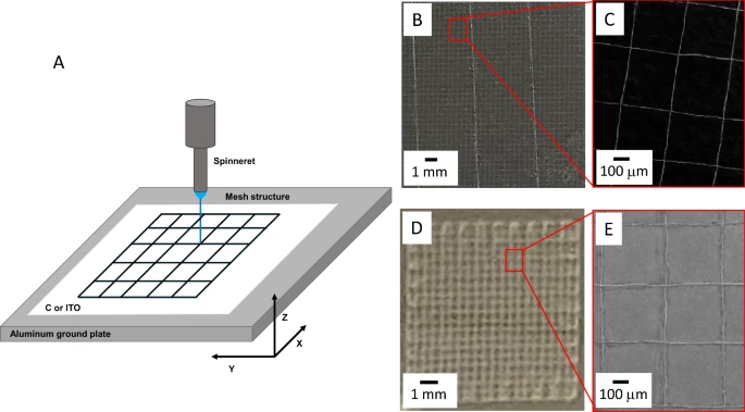
Figure 2. (A) Schematic drawing of the near-field writing and assembly of single strand nanofiber into sub-millimeter mesh pattern on conducting (B) and (C) carbon and (D) and (E) ITO glass. (B) Optical microscope picture of 20 × 20 mm2 mesh with (C) scanning electron microscope (SEM) image showing 120 nm PEO nanofiber with a line-to-line grip pitch of 500 mm. Note: The near-field writing was done at a 2 kV and 3 mm spinneret height (z) at a writing speed of 18 mm/s. (D) Optical microscope image of a 10 × 10 mm2 mesh and (E) scanning electron micrograph (SEM) showing 150 nm PEO nanofiber with a line-to-line grip pitch of 500 mm. Note The near-field writing was done at a 3.2 kV and 4 mm spinneret height (z) at a writing speed of 15 mm/s. The z-axis varies ± 10 mm to maintain electrical field. © Calzado‑Delgado, M., Yeung, K. L. et al. (2022)
Observations
Large-Area Electrospinning
Electrospun fibers were deposited homogeneously in the form of a fiber mat over a large area with uniform thickness by programming the x-y movement and raster movement. The HPMC nanofibers demonstrated excellent skin adhesion and biocompatibility, while the PVA exhibited exceptional potential for releasing and storing drug molecules. The HPMC/PVA/HPMC sample displayed cell viability, effectively promoted wound healing, and prevented infection when used as a wound dressing.
The two 5.2 μm thick HPMC layers containing 110 ± 20 nm nanofibers provided structural support to the 30.5 mm thick electrospun PVA layer containing 200 ± 40 nm nanofibers. The fibers were effective in gradually releasing amoxicillin/clavulanic acid, with more than 94.8% of the loaded active components being released after seven days. The nanofibers also displayed exceptional bactericidal activities against E. faecalis, S. aureus, and E. coli.

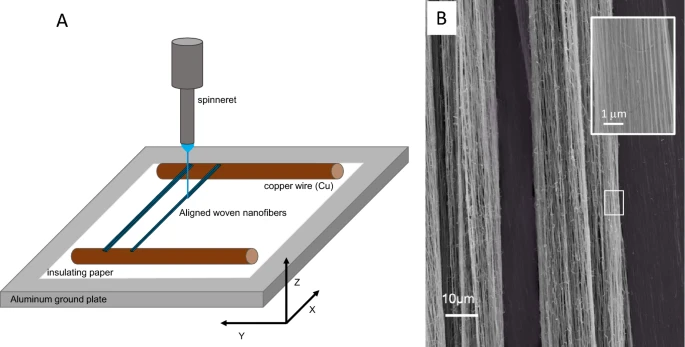
Figure 3. (A) Schematic drawing of the near-field electrospinning of PVA nanofiber between parallel copper wires to create (B) aligned strands 130 ± 12 nm PVA nanofiber by varying the voltage between 1.8 and 2.8 kV, spinneret height of 3 mm, x-axis movement speed of 20 mm/s and y-axis movement of 20 µm/min. © Calzado‑Delgado, M., Yeung, K. L. et al. (2022)
Near-Field Nanofiber Writing
A single strand of 120 nm PEO nanofiber was accurately drawn into a 500 mm mesh on the carbon substrate using the electrospinning equipment at 18 mm/s speed in 100 s. All strands in the mesh were intercepted perpendicularly and remained perfectly aligned. Similarly, the PEO nanofibers were also written on the conducting ITO glass, which indicated their potential in microelectronic fabrication.
Furthermore, the electrospun mesh was detached from the substrate to use it as a sieve filter for particles, such as droplets and aerosols with sizes of 0.1 to 10 μm, to prevent airborne transmission of respiratory diseases. However, the filtration efficiency depended on the opening size of the mesh, with finer mesh openings leading to higher filtration efficiency.
Near-Field Printing of 3D Micro- and Nanostructures
The PEO nanofibers were precisely printed on the copper wire surface through near-field printing. The nanofibers were also printed atop each other to create a 43 ± 0.1 µm high printed feature over the copper wire surface at 18 mm/s printing speed. Additionally, a nanostructure containing 140 strands of 102 ± 10 nm PEO nanofiber was printed over the copper wire at 300 mm/s printing speed.
To summarize, the findings of this study demonstrated that the new electrospinning equipment can effectively operate in both near- and far-field conditions to perform direct writing of nanofibers into the micron and millimeter-scale patterns, 3D nano- and microstructure printing, and large-area deposition of electrospun fibers with control and precision.
Reference
Calzado‑Delgado, M., Yeung, K. L. et al. (2022) A new versatile x–y–z electrospinning equipment for nanofiber synthesis in both far and near field. Scientific Reports. https://www.nature.com/articles/s41598-022-08310-0#Abs1
Disclaimer: The views expressed here are those of the author expressed in their private capacity and do not necessarily represent the views of AZoM.com Limited T/A AZoNetwork the owner and operator of this website. This disclaimer forms part of the Terms and conditions of use of this website.